


TCA BMS-16S200A-20A Alkaline Battery Pack Battery Management System
1. Functional Features
High-integrated analog front-end Adjustable overcurrent protection
Isolation of the power supply circuit Has a variety of dormancy and awakening modes
Integrated serial port IC Low power consumption
High Voltage Accuracy (≤10mV) RS485 Communication
High Current Accuracy (≤2%@FS) Adjustable Parameter Settings
4-Way Battery Temperature Detection (≤2°C) Data Refresh Interval (Period) ≤ 2 Seconds
SOC Estimation Function LED Status Indication Function
SOH Estimation Function Charge Equalization Function
Short Circuit Protection Function SOC Accuracy (≤5% @ 50% Capacity Range Or More)
2. Functional Block Diagram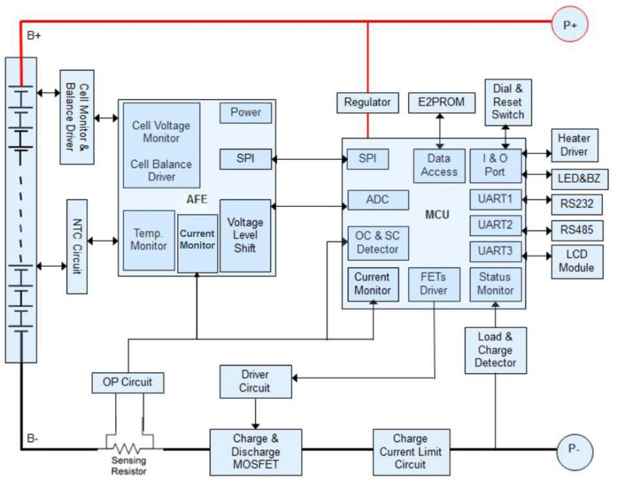
3. Environmental Requirements
| Projects | Parameters | Unit |
| Operating Temperature | -20 to 75 | ℃ |
| Storage Temperature | -40 to 75 | ℃ |
| Operating Humidity | ≤95 (45°C±2°C) | %RH |
| Storage Humidity | ≤90 (45°C±2°C) | %RH |
| Temperature Measurement | -40 to 125 | ℃ |
| Atmospheric Pressure | 70~106 | kPa |
4.Install connection instructions:
There are strict sequence requirements on the protection board. First weld B-, P-, B +, P +, and plug in the battery sampling line connector in order from low to high. After power on, charge or button activation. Load or charger can be added after all cables are installed.
When removing, first unplug the charger or load, remove the battery sampling line connector in the order from high to low, and finally remove B +, P +, B-and P-.
5. Precautions for use:
1) When connecting the battery lead, note not to misconnect or reverse connect. If the wrong lead is connected, it may cause damage to this circuit board, which should be re-tested again before use.
2) When assembly, the protective plate is careful not to directly contact the surface of the cell to avoid damage to the cell. Ensure the assembly.
3) In the process of use, pay attention to the lead head, soldering iron, solder and other components do not touch the components on the circuit board, otherwise it may lead to damage to the protection board.
4) The use process should pay attention to anti-static, moisture-proof, waterproof and other measures.
5) Please follow the designed parameters and the conditions of use during the use process, and do not exceed the relevant values in this specification, otherwise it may lead to damage to the protection plate.
6) After combining the battery pack and the protection panel, if there is no voltage output or no charge for the first time, please re-check whether the wiring is correct.