


High-integrated front-end Adjustable overcurrent protection
Isolation of the power supply circuit Has a variety of dormancy and awakening modes
Integrated serial port IC Low power consumption
High Voltage Accuracy (≤10mV) RS485 Communication
High Current Accuracy (≤2%@FS) Adjustable Parameter Settings
4-Way Battery Temperature Detection (≤2°C) Data Refresh Interval (Period) ≤ 2 Seconds
SOC Estimation Function LED Status Indication Function
SOH Estimation Function Charge Equalization Function
Short Circuit Protection Function SOC Accuracy (≤5% @ 50% Capacity Range Or More)
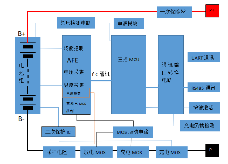
2.Functional Block Diagram
3.Environmental Requirements
| Projects | Parameters | Unit |
| Operating Temperature | -20 to 75 | ℃ |
| Storage Temperature | -40 to 75 | ℃ |
| Operating Humidity | ≤95 (45°C±2°C) | %RH |
| Storage Humidity | ≤95 (45°C±2°C) | %RH |
| Temperature Measurement | -40 to 125 | ℃ |
| Atmospheric Pressure | 70~106 | kPa |
4.Note for installing the protective plate
1) Connect the communication port CN1 or CN3 according to the wiring diagram of the protection board;
2) connect the total negative electrode of the cell to the B-of the protection plate;
3) Connect the total positive electrode of the cell to the B + terminal of the protection plate;
4)Connect the cell B0.B1.B2.B3.B4.B5.B6.B7 to the protection board J3;
5) The negative of the load / charger is directly connected to the positive electrode of the protection plate P-;
6) The positive electrode of the load / charger is directly connected to the positive electrode P + of the protection plate;
7)Charging activation / communication activation / button activation;
5.Step of removing the protective plate:
1)Remove the communication port CN1 or CN3;
2) Remove the connection line of the P + load / charger positive electrode on the protection plate;
3)Remove the connection cable of the P-load / charger anode on the protection board;
4) Remove the cell B7.B6.B5.B4.B3.B2.B1.B0 on the protective plate in sequence;
5)Remove the total positive B + connection line of the cell;
6)Finally, remove the connecting line of the total negative B-of the cell.